System Architecture and Execution Model
To understand the execution in the navigational integration more
clearly, we use the below figures to explain the execution steps in
the navigational integration. The integration in this example uses two
WISs. The first step shown in Figure (1) is the navigation from the
front page to the result page of the first WIS. The second step shown
in Figure (2) is the navigation from the result page of the first WIS
to the result page of the second WIS. The sub-figure shown in the
left side of each figure is the result that is seen by the user on his
browser.
Each area has a main information resource (MIR) as a
yellow-page server. In MIR, it has a wrapper module and a
proxy executor. The wrapper describes client applications of its WISs
in a common (object-oriented) data model; that is, the data and access
methods of a client application are described by interface
definitions (ID). In addition, each area has a local area
repository that maintains interface definitions of its maintained WISs
as well as the local domain hierarchy defining semantic information of
data used in its area. All areas in the same region also share a
region repository that manages the domain hierarchy information for
resolving semantic conflicts among them.
Under these preparations, while moving, a mobile user works as
follows: firstly, he sets connection to the network and downloads IDs
of some interesting WISs with a minimal set of domain rules
into his PDA. Subsequently, the user disconnects his PDA from the
network, and activates the matcher on the PDA. Then the
matcher uses the downloaded IDs and domain-related rules to resolve
semantic conflict among heterogeneous data, and helps the user to
define navigational integration in a query command. Finally, the user
again sets connection to the network, and materializes navigational
integration by sending the query command to a proxy executor from the
PDA.

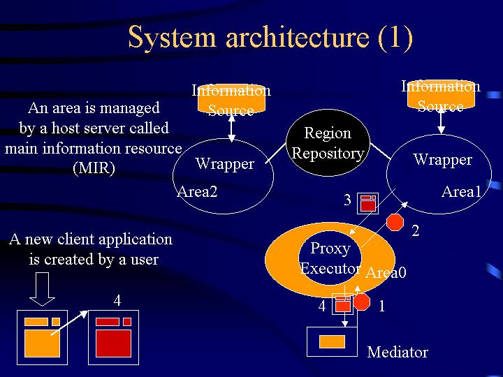
Figure (1) shows the steps of execution of the navigation from the
front page to the result page of the first WIS.
- Step 1: The user sends the query command to any MIR (a MIR
of area0 in this figure) by clicking the link that the query command
was embedded.
- Step 2: At this MIR, the proxy executor then receives the
query, registers the command into its system as an executable object,
analyzes the query into several sub-queries, and sends a sub-query to
the MIR of the first WISs managed in area1.
- Step 3: The proxy executor of the area1 executes the
sub-query by sending it to the corresponding wrapper. The wrapper gets
a result page from the WIS, and extracts data in the page to generate
objects in the common data model. After that, the wrapper embeds the
objects into the result page for marking positions of data. The result
page is sent back to the MIR of area0 again.
- Step 4: The proxy executor receives the result page,
embeds the derived links for activating the next step of the
navigational integration into the position of data marked earlier, and
sends the result page back to the user again.
From the user's view point, he sees only the step (1) and (4) as shown
at the lower left conner.

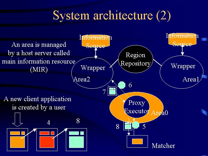
Figure (2) shows the execution of the navigation from the result page
of the first WIS to the result page of the second WIS.
- Step 5: Similar to the first step, first, the user clicks
the derived links for retrieving the relevant information he
wants. The embedded command in that link is sent to the proxy executor
of area0 again.
- Step 6: The proxy executor of area0 restarts the execution
that it has registered at the first step according to the parameters
sent with this request. It sends the request to the next MIR in area2.
- Step 7: Likewise the execution in area1, area2 returns
the result to the MIR of area0.
- Step 8: Finally, the proxy executor returns the result page
of the second WIS to the user.


